Peltier Module Electric Diagram Circuit Diagram A sensor will control the alimentation by turning the Peltier module on and off, depending on the settings. Check the wire diagram at the end of this post to see how to connect everything to the Peltier device and the power supply. The TEC-12706 Peltier module can in theory use up to 6 amps, so it needs a good power supply.

This TEC1-12706 module and the Peltier effect makes the perfect DIY cooler! This instructable is a step-by-step tutorial showing you how to make your homemade cooler. This DIY fridge uses the Peltier effect, which is the presence of heating or cooling at an electrified junction of two different conductors.
Mini Peltier Air Conditioner (Plans) : 13 Steps Circuit Diagram
To use a Peltier module in a circuit: Identify the hot and cold sides of the module. Connect the positive terminal of the power supply to the positive (V+) pin of the Peltier module. Connect the negative terminal of the power supply to the negative (V-) pin of the Peltier module. Apply the appropriate voltage as per the module's specifications.

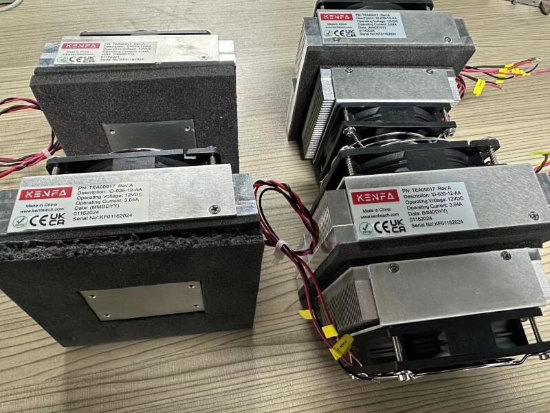
#unboxing peltier #thermoelectric module assembly #peltier kit assembly🔸(Available now for best prices) Buy peltier module here: https://amzn.to/311STA9 Buy

how to make peltier air conditioner peltier module Circuit Diagram
Peltiers: The core of the cooling system. Heatsink: Helps dissipate heat generated. Cooling Fan: Enhances heat expulsion. LCD Display and Keypad: For user interface. How It Works. Initial Setup: First, assemble the electronic system complete with an LCD display and a 4 x 1 keypad. This allows the user to set the minimum and maximum temperatures A Peltier Module (TEC1-12706) with wires attached. Now you can build yourself a mini Refrigerator using the Peltier devices and a few other simple components. Peltier effect modules can also be used for temperature control for applications like cooling in electronic devices, circuits, and systems where a low budget and lightweight cooling