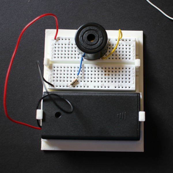
Designing a buzzer circuit that waits a bit before turning on Circuit Diagram Today I am showing you how to make simple buzzing circuit Buzzer Circuits on a breadboard.I am in no way a expert in electrical engineering but I just wante

The simple piezo buzzer circuit described here actually works in a quite unique way. Instead of the normal working concept employed by other forms of oscillators which require resistor and capacitor networks for generating the oscillations, this circuit use inductive feedback for the required operations.

Simple Buzzer Circuit : 3 Steps Circuit Diagram
Figure 1: simple electronic buzzer circuit diagram using two-transistor. By has both resistors- R=1.2K and C=0.047uF to set the output frequency. Which can change slightly the value of both components, so the output sound changed. However, from the experiments, this value will be the best frequency.

Simple Buzzer Circuit: The following items are required to build this circuit: 9-Volt Battery Snap 9-Volt Battery Two wires DC Buzzer Breadboard Projects Contests Teachers Simple Buzzer Circuit. By 624117 in Circuits Electronics. 7,039. 1. 2. Introduction: Simple Buzzer Circuit
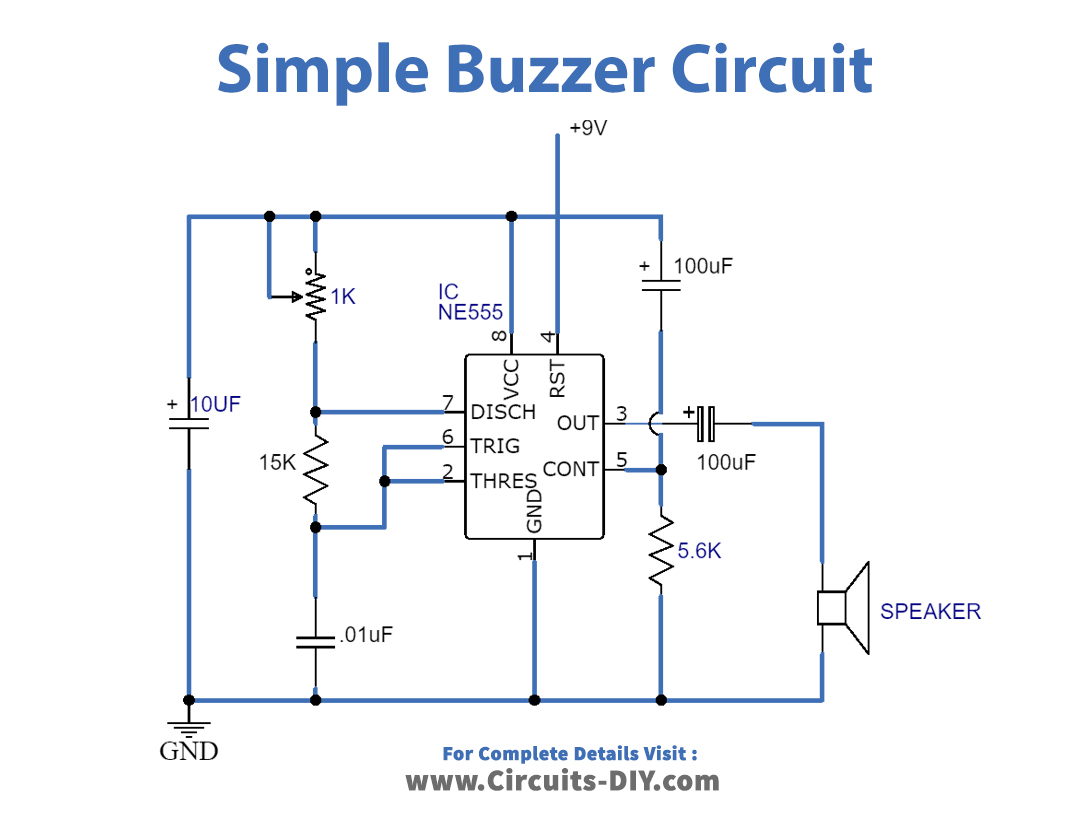
Simple Buzzer Circuit with NE555 IC Circuit Diagram
A buzzer is a high frequency oscillator circuit designed to produce a buzzing sound via a transducer or speaker output. Simple Buzzer using a Single Transistor With just a single transistor, a ferrite inductor, and a piezo transducer, you can create a circuit that will "buzz" or, more accurately, "tweet" for you, potentially producing a A buzzer circuit is an electronic device that produces an audible sound when activated. Buzzer circuits are widely used in various applications, such as alarms, timers, and user interfaces. In this article, we will explore the basics of buzzer circuits, how to create a simple buzzer circuit, and ways to enhance the design for improved