Analysis of BMS Battery Management System Protection Mechanism and Circuit Diagram 3S Battery Management System (BMS) circuit for lithium-ion batteries. The 3S configuration is a series connection of three cells, requiring a robust BMS to ensure balanced charging, overcharge protection, and efficient power delivery. We'll focus on a straightforward yet highly effective design using the TL431 Zener diode, BD140 PNP
The ongoing transformation of battery technology has prompted many newcomers to learn about designing battery management systems. This article provides a beginner's guide to the battery management system (BMS) architecture, discusses the major functional blocks, and explains the importance of each block to the battery management system. Figure 1. Protection Features of 4S 40A BMS Circuit Diagram. A BMS is essential for extending the service life of a battery and also for keeping the battery pack safe from any potential hazard. The protection features available in the 4s 40A Battery Management System are: Cell Balancing; Overvoltage protection; Short circuit protection; Undervoltage

Lithium Ion Battery Management and Protection Module (BMS ) Teardown ... Circuit Diagram
This is a BMS that uses an MCU with proprietary firmware running all of the associated battery-related functions. The Building Blocks: Battery Management System Components. Look back at Figure 1 to get an overview of the fundamental parts crucial to a BMS.

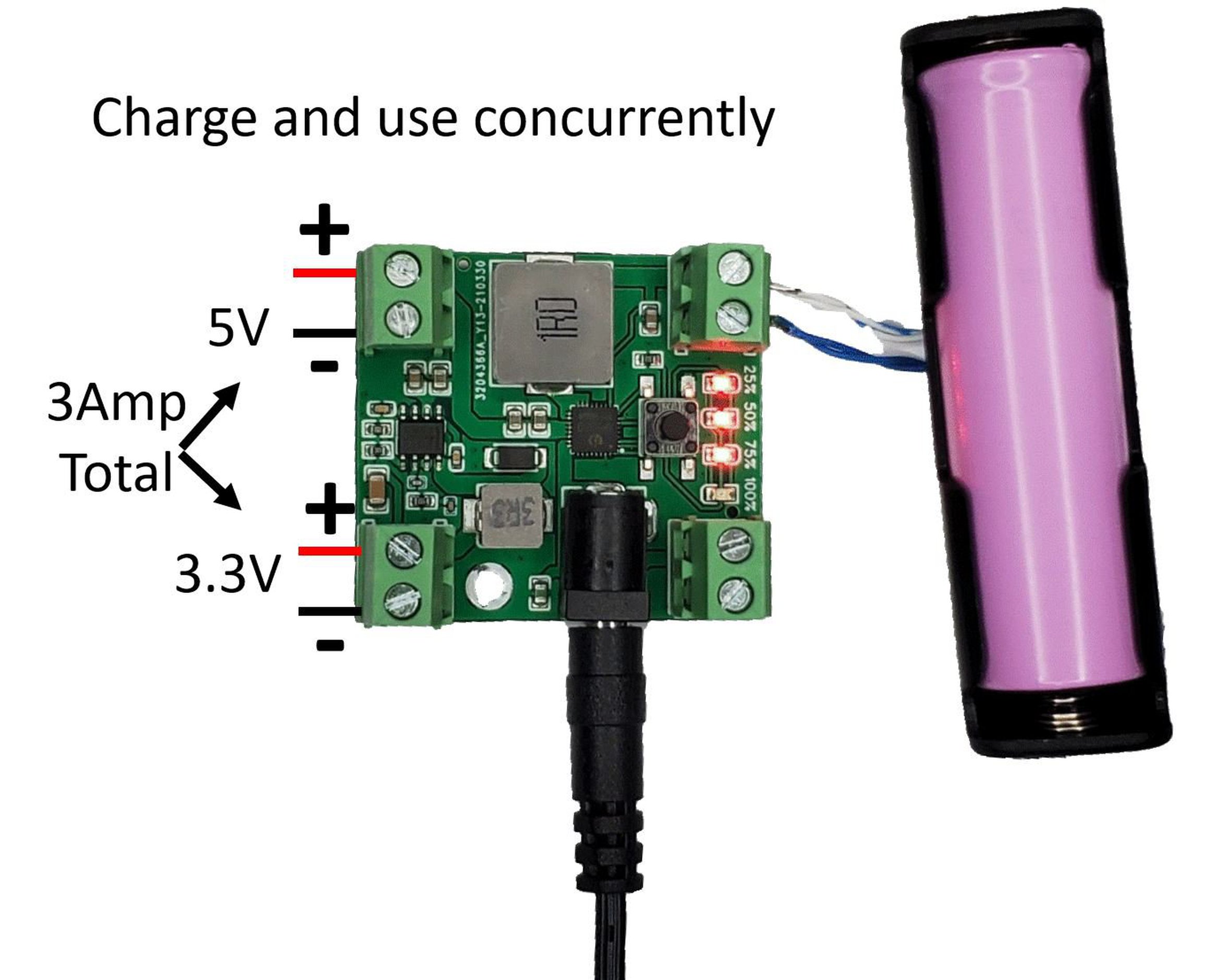
A Battery Management Unit (BMU) is a critical component of a BMS circuit responsible for monitoring and managing individual cell voltages and states of charge within a Li-ion battery pack. The BMU collects real-time data on each cell's voltage and state of charge, providing essential information for overall battery health and performance. A battery management system oversees and controls the power flow to and from a battery pack. During charging, the BMS prevents overcurrent and overvoltage. The constant-current, constant-voltage (CC-CV) algorithm is a common battery charging approach used in a battery management system. That's why these batteries should go together with a battery management system unit or BMS. This will control the voltage and current from the battery and keep them safe. Usually, the nominal voltage of a LIPO battery is 3.8 volts and 4.2V when fully charged. With this circuit, we can charge a 3S battery for example and all individual
Introduction to Battery Management Systems Circuit Diagram
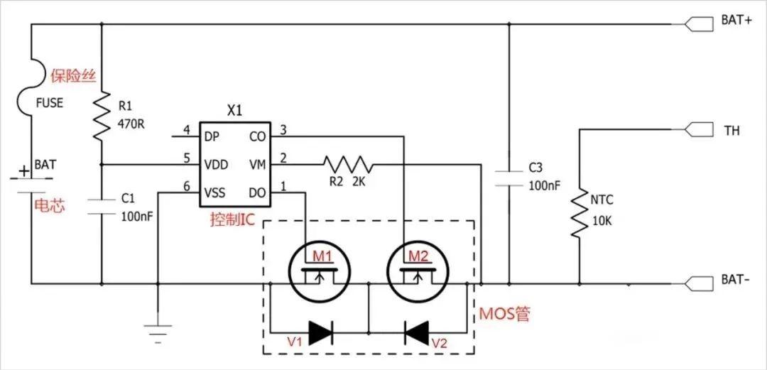
This circuit measures the amount of current flowing in and out of the battery pack, enabling accurate estimation of the state of charge and detecting any abnormal current conditions, such as a short circuit. Key Functions of a Battery Management System: Battery Monitoring: The BMS continuously monitors the voltage and current of each A battery management system comprises various components, including the battery monitoring unit, control unit, protection circuit, cell balancing circuit, and communication interface. Together, these components ensure the safe, efficient, and optimal performance of the battery pack, prolonging its lifespan and preventing any potential hazards.